
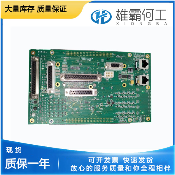
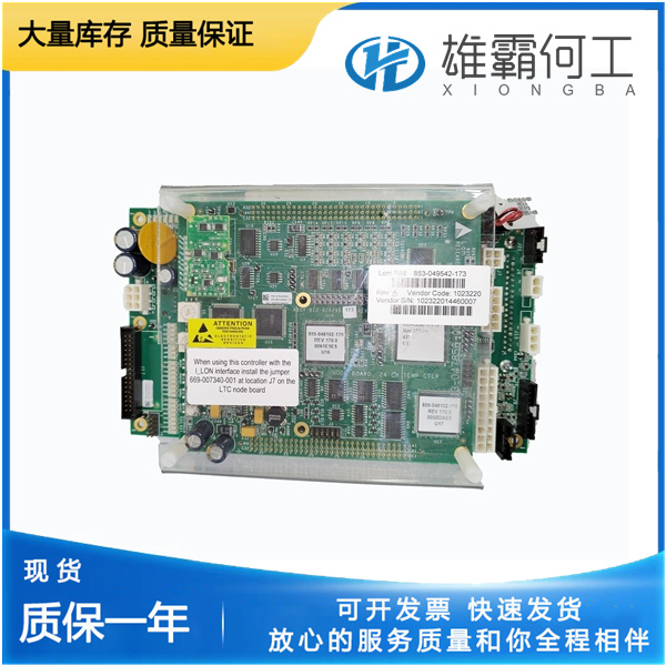
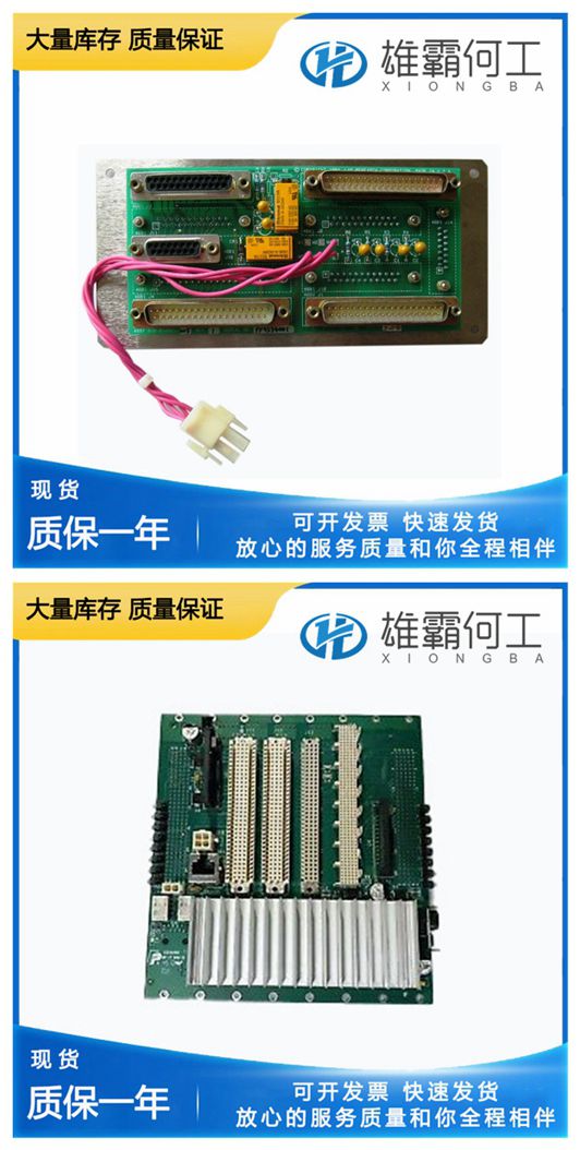
LAM 810-810193-103 半导体配件
853-085372-114在通过串行通信端口连接到控制系统的PC上运行。工程工作站PC可以永久连接到控制装置,也可以仅在需要时连接。通信服务器Servlink I/O server包含在与监视窗口相同的安装中。Watch Window是典型的853-085372-114应用程序,它提供了强大而直观的界面。853-085372-114用户熟悉菜单结构。通过资源管理器窗口提供变量导航,类似于853-085372-114中的资源管理器。监视窗口执行三个主要功能:监视和调整控制变量--监视窗口以表格格式显示变量。用户在任何给定时间选择要查看的变量。可以创建多个变量页面,每个页面都有用于各种故障排除或调整过程的有用参数。用户可以根据正在执行的任务在页面之间切换。控制配置和设置点管理——监视窗口可以从控制系统上传或下载所有可调变量。此功能允许用户(例如,车队所有者、经销商、包装商)从一个控件上传(和保存)所有可调参数,853-085372-114并将相同的设置下载到类似发动机配置的其他控件。程序加载--监视窗口提供将新程序下载到控件的服务。这仅在专业版中可用853-085372-114
PXI背板本地总线是菊花链总线,它将每个外围插槽与左右相邻的外围插槽连接起来,如图1-6所示。背板在所有插槽之间路由PXI本地总线6。来自槽1的左局部总线6不在任何地方路由,而来自槽18的右局部总线信号不在任何位置路由。本地总线信号的范围可以从高速TTL信号到高达42V的模拟信号。初始化软件使用每个相邻外围模块特有的配置信息来评估本地总线兼容性。PXI触发总线同一PXI总线段上的所有插槽共享八条PXI触发线。您可以通过多种方式使用这些触发行。例如,您可以使用触发器来同步几个不同PXI外围模块的操作。在其他应用中,位于系统时序槽中的一个模块可以仔细地控制对系统中的其他模块执行的定时操作序列。模块可以相互传递触发器,允许对系统正在监视或控制的异步外部事件进行精确定时的响应。
Static trigger routing (user-specified line and directional assignments) can be configured through Measurement & Automation Explorer National Instruments | 1-11 NI PXIe-1085 Series User Manual (MAX). Dynamic routing of triggers (automatic line assignments) is supported through certain National Instruments drivers like NI-DAQmx. Note Although any trigger line may be routed in either direction, it cannot be routed in more than one direction at a time.
 b
b
In other applications, one module located in the system timing slot can control carefully timed sequences of operations performed on other modules in the system. Modules can pass triggers to one another, allowing precisely timed responses to asynchronous external events the system is monitoring or controlling. The PXI trigger lines from adjacent PXI trigger bus segments can be routed in either direction across the PXI trigger bridges through buffers. This allows you to send trigger signals to, and receive trigger signals from, every slot in the chassis.
The PXI backplane local bus is a daisy-chained bus that connects each peripheral slot with adjacent peripheral slots to the left and right, as shown in Figure 1-6. The backplane routes PXI Local Bus 6 between all slots. The left local bus 6 from slot 1 is not routed anywhere and the right local bus signals from slot 18 are not routed anywhere. Local bus signals may range from high-speed TTL signals to analog signals as high as 42 V. Initialization software uses the configuration information specific to each adjacent peripheral module to evaluate local bus compatibility. PXI Trigger Bus All slots on the same PXI bus segment share eight PXI trigger lines. You can use these trigger lines in a variety of ways. For example, you can use triggers to synchronize the operation of several different PXI peripheral modules.