
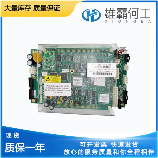
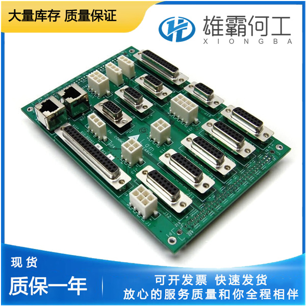
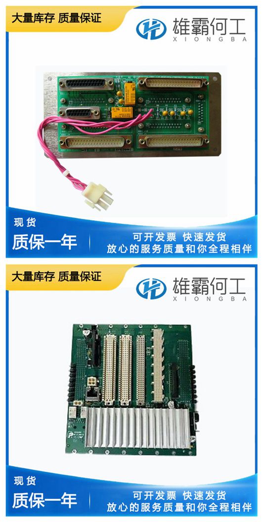
LAM 853-190023-001 电源平面
用户有责任确保环境温度不超过附录A“规范”中规定的额定环境温度。如果温度超过规定的规格,温度指示灯将闪烁红色,如本章前面板和风扇模块指示灯部分所述。设置风扇速度风扇速度选择开关位于853-190023-001系列机箱的后面板上。请参阅图1-2,853-190023-001系列机箱的后视图,以定位风扇速度选择开关。选择“高”可获得最大冷却性能,选择“自动”可提高声学性能。当设置为Auto(自动)时,风扇转速由底盘进气温度决定。高振动环境的注意事项在高振动环境中获得最佳性能;使用2号十字螺丝刀将模块化电源螺钉和电源换向安装螺钉拧紧至11.5 lb·in.(1.3 N·m)。有关螺钉位置,请参见图3-1,拆卸电源换向。安装填充面板要保持模块的正确冷却性能,请将填充面板(随机箱提供)安装在未使用或空的插槽中。用提供的固定安装螺钉固定。安装插槽挡板可以通过安装可选的插槽挡板来提高机箱的冷却性能。有关更多详细信息,
853-190023-001系列机箱设计用于在工作台或仪器架上操作。底盘必须水平放置,以便在台式机上使用。不支持机箱手柄向上的垂直方向配置。无论配置如何,都必须提供以下章节中概述的冷却间隙。提供足够的间隙853-190023-001系列的主冷却排气口位于机箱顶部。主进风口位于底盘后部。辅助进风口和排气口位于底盘侧面。机箱与周围设备或堵塞物之间必须保持足够的间隙,以确保机箱电源以及插入机箱的模块得到适当冷却。这些间隙如图2-1所示。853-190023-001系列机箱的通风口853-190023-001。未能提供这些间隙可能会导致机箱或模块出现与热相关的故障。机箱环境温度定义机箱风扇控制系统在自动风扇转速模式下使用进气温度作为控制风扇转速的输入。因此,机箱环境温度被定义为机箱后部风扇进气口外的温度。注意,该温度可能高于环境室温,这取决于周围设备和/或存在的堵塞。
Considerations for High Vibration Environment For the best performance in a high vibration environment; tighten the modular power supply screws and the power supply shuttle mounting screws to 11.5 lb · in. (1.3 N · m) using a #2 Phillips screwdriver. 853-190023-001See Figure 3-1, Removing Power Supply Shuttle, for screw locations. Installing Filler Panels To maintain proper module cooling performance, install filler panels (provided with the chassis) in unused or empty slots. Secure with the captive mounting screws provided. Installing Slot Blockers The cooling performance of the chassis can be improved by installing optional slot blockers. Refer to ni.com for more details.853-190023-001
Because of this, the chassis ambient temperature is defined as the temperature that exists just outside of the fan intake vents on the rear of the chassis. Note that this temperature may be higher than ambient room temperature depending on the surrounding equipment and/or blockages present.853-190023-001 It is the user’s responsibility to ensure that this ambient temperature does not exceed the rated ambient temperature as stated in Appendix A, Specifications. If the temperature exceeds the stated spec, the temperature LED blinks red, as discussed in the Front Panel and Fan Module LED Indicators section of this chapter. Setting Fan Speed The fan-speed selector switch is on the rear panel of the NI PXIe-1085 Series chassis. Refer to Figure 1-2, Rear View of the NI PXIe-1085 Series Chassis, to locate the fan-speed selector switch. Select High for maximum cooling performance or Auto for improved acoustic performance. 853-190023-001When set to Auto, the fan speed is determined by chassis intake air temperature.

The NI PXIe-1085 Series chassis is designed to operate on a bench or in an instrument rack. The chassis must be oriented horizontally for benchtop use.853-190023-001 Vertical orientation with the chassis handle up is not a supported configuration. Regardless of the configuration, you must provide the cooling clearances as outlined in the following sections. Providing Adequate Clearance The primary cooling exhaust vent for the NI PXIe-1085 Series is on the top of the chassis.853-190023-001 The primary intake vent is on the rear of the chassis. The secondary intake and exhaust vents are located along the sides of the chassis. Adequate clearance between the chassis and surrounding equipment or blockages must be maintained to ensure proper cooling of the chassis power supply as well as the modules plugged into the chassis.853-190023-001 These clearances are outlined in Figure 2-1. The vent locations for the NI PXIe-1085 Series chassis are shown in Figure 2-2. Failure to provide these clearances may result in thermal-related failures in the chassis or modules.Chassis Ambient Temperature Definition The chassis fan control system uses intake air temperature as the input for controlling fan speeds when in Auto Fan Speed mode.