
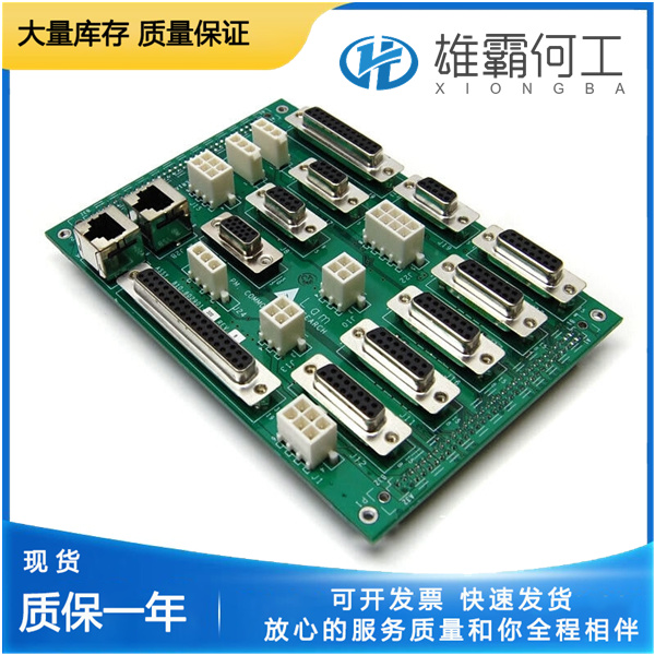
LAM 853-190023-001 平面分开
为了帮助系统集成商,PXI Express机箱和系统模块的制造商必须记录其产品的功能。.ini文件包含最低文档要求,这些文件由ASCII文本组成。系统集成商、配置实用程序和设备驱动程序可以使用这些.ini文件。NI PXIe-1085系列机箱的功能说明文件包含在机箱附带的软件介质上的chassis.ini文件中。此文件中的信息与系统控制器的信息相结合,可创建一个名为pxisys.ini(PXI系统初始化)的系统初始化文件。系统控制器制造商为包含系统控制器的特定机箱型号提供一个pxisys.ini文件,或者提供一个实用程序,可以读取任意的chassis.ini文件并生成相应的pxisys ini文件。NI的系统控制器为NI PXIe-1085系列机箱提供了pxisys.ini文件,因此不需要使用chassis.ini文件。
一些National Instruments机箱,如NI PXIe-1085系列和NI PXI-1044/1045,能够使用MAX中的触发器路由选项卡将触发器从同一机箱内的一条总线路由到另一条总线,如图2-10所示。注意:选择任何未禁用的路由都会自动保留要路由到的所有触发总线中的线路。如果您使用NI DAQmx,它会为您保留和路由触发线路,因此您不必手动路由触发线路。完成以下步骤以在MAX.1中配置触发器路由。在配置树中,选择要在其中路由触发线路的机箱。2.在右侧窗格中,选择底部附近的触发器路由选项卡。3.对于每条触发线,选择“向右布线”、“从中间向外布线”或“向左布线”以在所述方向上布线该线上的触发器,或者选择“禁用”作为不使用手动布线的默认行为。4.单击“应用”按钮。使用系统配置和初始化文件PXI Express规范允许PXI Express机箱和系统模块的多种组合。
Some National Instruments chassis, such as the NI PXIe-1085 Series and the NI PXI-1044/1045, have the capability to route triggers from one bus to others within the same chassis using the Trigger Routing tab in MAX, as shown in Figure 2-10. Note Selecting any non-disabled routing automatically reserves the line in all trigger buses being routed to. If you are using NI-DAQmx, it will reserve and route trigger lines for you, so you won’t have to route trigger lines manually. Complete the following steps to configure trigger routings in MAX. 1. In the Configuration tree, select the chassis in which you want to route trigger lines. 2. In the right-hand pane, select the Trigger Routing tab near the bottom.
PXI-1 System Configuration 1. Launch MAX. 2. In the Configuration tree, click the Devices and Interfaces branch to expand it. 3. If the PXI system controller has not yet been configured, it is labeled PXI System (Unidentified). Right-click this entry to display the pop-up menu, then select the appropriate system controller model from the Identify As submenu. 4. Click the PXI system controller. The chassis (or multiple chassis, in a multichassis configuration) is listed below it. Identify each chassis by right-clicking its entry, then selecting the appropriate chassis model through the Identify As submenu. Further expanding the PXI System branch shows all devices in the system that can be recognized by NI-VISA. When your system controller and all your chassis are identified, the required pxisys.ini file is complete.
PXI-1 System Configuration 1. Launch MAX. 2. In the Configuration tree, click the Devices and Interfaces branch to expand it. 3. If the PXI system controller has not yet been configured, it is labeled PXI System (Unidentified). Right-click this entry to display the pop-up menu, then select the appropriate system controller model from the Identify As submenu. 4. Click the PXI system controller. The chassis (or multiple chassis, in a multichassis configuration) is listed below it. Identify each chassis by right-clicking its entry, then selecting the appropriate chassis model through the Identify As submenu. Further expanding the PXI System branch shows all devices in the system that can be recognized by NI-VISA. When your system controller and all your chassis are identified, the required pxisys.ini file is complete.