
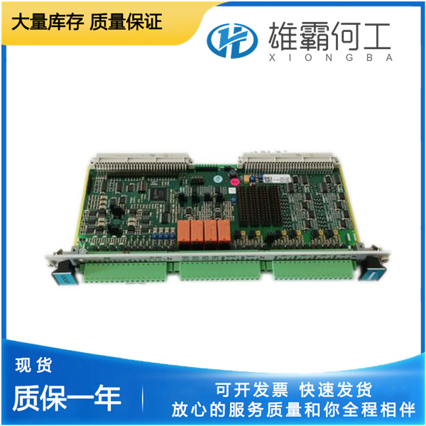
VM600 IOCN PNR200-566-000-112的操作指南
VM600 IOCN PNR200-566-000-112 Operation Guide
(Vibro-Meter Mechanical Protection System Module)
1. Physical Installation
Mounting
Secure to DIN rail (EN 60715 standard) using torque-controlled fasteners (0.6 Nm ±0.1 Nm)26. Ensure lateral shift ≤0.5mm for connector alignment2.
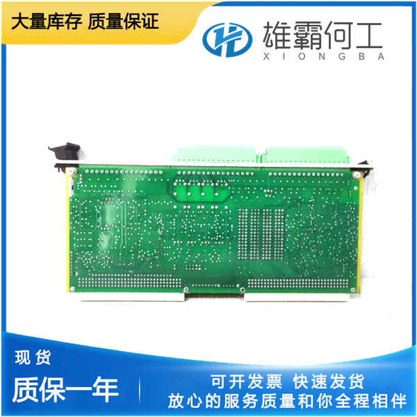
Environmental Requirements
Operating range: -25°C to +55°C; humidity ≤95% non-condensing26. Requires IP54 enclosure for harsh environments (e.g., turbine nacelles)5.
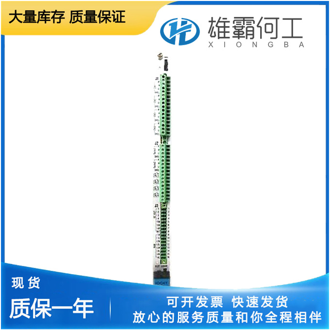
2. Electrical Wiring
plaintextCopy Code[Terminal Configuration]
• Safety Inputs (S11-S12): PNP/NPN configurable, 18-30V DC
• Dynamic Signal Inputs: IEPE-compatible (4-20mA)
• Ethernet Port: RJ45 (10/100BASE-T)

[Critical Practices]
→ Shielded twisted pairs for analog signals :ml-citation{ref="1,7" data="citationList"}
→ Ground shield at single point only :ml-citation{ref="4" data="citationList"}
→ Separation ≥100mm from power cables :ml-citation{ref="2" data="citationList"}3. Network Integration
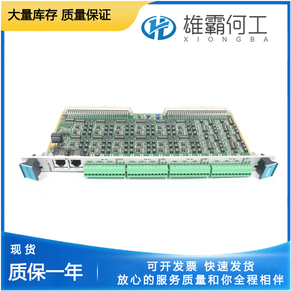
Protocol Setup
Configure via VM600 CPUM software:iniCopy Code[COMM_Protocol] Type=PROFINET ; Alternatives: PROFIBUS, Ethernet/IP Update_Rate=8ms ; Min cycle time Node_ID=0x20 ; Unique address
Supports real-time data exchange with PLCs (e.g., Siemens S7-1500)14.
Diagnostic Verification
4. Operational Workflow
Power-Up Sequence
- Apply 24V DC (19.2-30V range)2
- Wait for SYSTEM READY LED (green steady)6
- Initialize sensors via VM600 ConfigTool1
Runtime Monitoring
- Track vibration thresholds (API 670 compliance)4
- Use MODBUS register 40012 for real-time RPM data1
- Enable auto-triggering for >5% overspeed events3
Safety Interlocks
textCopy CodeEmergency Stop Logic:
  S11──┤ESTOP├──S12  → Output de-energizes within 50ms
Test monthly via forced fault simulation27.
5. Maintenance & Troubleshooting
Preventive Actions
- Annual contact inspection (mechanical life: 10⁷ ops)6
- Clean air vents quarterly (ΔT >10°C indicates clogging)5
Common Faults